
If you’ve just gotten your Shapeoko 3 hobby CNC, or if you’re anxiously waiting for it’s arrival you may find yourself exploring Carbide Create, the free CAD/CAM software provided by Carbide 3D. Create is a basic but fairly robust entry point into the world of CNC machining. While it lacks some of the advanced features of competitors like Fusion 360 or Vectric’s suite of products, it’s capable of a lot more than many give it credit for.
Its simplicity comes with an unfortunate lack of intuitiveness, settings are spread across multiple screens and there are no wizards or dialogs to setup new projects or perform common tasks. With that in mind I offer below a setup process to help you setup your first CNC project in Carbide Create.
Job Setup
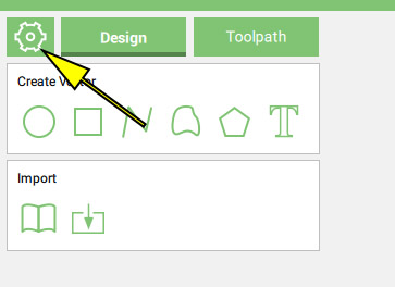 After opening Carbide Create enter the Job Setup screen by clicking the “gear” icon in the top left of the screen.
This will open the Job Setup sidebar and let us setup a number of important settings outlined below. I’m presenting the options not in the order they’re listed on screen but in the order I think you should enter them.
- Units – Near the bottom of the list is the toggle for switching between imperial (inches) and metric (millimeters). Since the rest of the measurements are contingent on this setting you might as well set this first. Changing the setting will convert existing values to their corresponding value in the other unit.
- Machine – You shouldn’t need to change this setting once you’ve set it to the correct setting, but select whether you’re operating a Shapeoko 3, Shapeoko 3 XL, or Shapeoko 3 XXL. This will limit the maximum stock size based on the cutting area of the machine.
Note: You can still draw outside the maximum allowed stock size and Create will output valid toolpaths. This allows flexibility for unusual setups but don’t expect Create to hold your hand here. If you draw outside the maximum bounds of your stock or of the machine itself make sure you understand what you’re doing.
- Stock Size – Here you’ll enter the size of the physical material you plan to cut. Width(X) is left to right as you look at the front of the machine, Height (Y) is front to back.
Your stock size doesn’t need to match your physical piece those it usually will. If you’re cutting a piece out of a larger board you may decide only to model in Create the area you’re concerned with.
- Stock Thickness – The final dimension of your stock, the thickness, is entered into the Stock Thickness field (duh). For many projects an accurate measurement of stock thickness is important and the use of digital calipers is recommended.
The dropdown under the Z entry is part of your Toolpath Zero (even though it’s not in the box of that title, as I said CC can be non-intuitive).
- Toolpath Zero – Your ‘zero point’ is how you will equate a point in your computer design with a point on your physical stock. You can choose any combination of zero locations but the most common are Top-Lower-Left and Top-Center. The only important aspect when selecting your zero point is that you can reliably, and often repeatable, locate that zero.
For the most part simply leave the defaults when starting out. A Toolpath Zero of Top, Lower-left means before carving you would move the gantry to the top of the workpiece in it’s lower left corner and zero the machine in Carbide Motion.
- Material – Select the most appropriate material for what you’re cutting. These are general categories and being close is fine. Carbide Create’s speeds are notoriously conservative even with the correct material chosen so you’re unlikely to have problems if you, for example, choose a hardwood when perhaps softwood would have been best.
- Document Background – Tucked away in it’s own separate screen are two handy settings. The background image option can be used to load an image into your background, this has no effect on the carving but you co could use it to trace a design.
Of more importance is the grid spacing. Even when set to inches the grid spacing defaults to an odd value of .197″, which many may recognize as 5mm. If you’re working in inches is makes more sense to adjust your grid to a .25″ or .125″ grid spacing value.
- Retract Height – Stepping back to the Job Setup screen the last setting to worry about is the Retract Height. This controls how high above the material the bit will be lifted as the router moves between cuts. It’s important that this setting be high enough for the bit to clear any clamps or other items on the machine that shouldn’t be hit by the bit. For those using the super-glue-and-painters-tape or double-stick-tape workholding method where nothing would be above the worksurface you can safely reduce this to 3-4mm.
Important: There’s an annoying habit in CC of this value being lost somewhat randomly based on mouse/keyboard input. Always verify this value before pressing Ok to leave the screen, and ideally check this again whenever you output toolpaths.